Drag
Drag
As an aircraft moves through the air, it encounters resistance. This resistance, known as drag, is one of the four fundamental aerodynamic forces alongside lift, thrust, and weight. Drag acts opposite to the direction of flight and must be overcome for sustained movement. Understanding drag is essential not only for optimizing aircraft performance but also for safe and efficient flight operations.
Drag can be classified into two primary categories:
-
Parasite Drag – Resistance associated with the aircraft design and shape.
-
Induced Drag – Resistance that is a byproduct of lift.
Each of these types includes various subcategories and behaviors, and their characteristics change with flight conditions such as speed, angle of attack (AOA), and proximity to the ground.
Parasitic Drag
Parasite drag is the resistance an aircraft experiences as it moves through the air. It includes all forms of aerodynamic resistance arising from the aircraft's shape, surface roughness, and the interaction of airflows around different components.
Parasite drag increases with the square of airspeed. Therefore, at high speeds, this form of drag becomes a dominant factor in total aerodynamic resistance.
Parasite drag is subdivided into three major types:
Form Drag
Form drag results from the shape and frontal area of components moving through the air. It is the resistance caused by the separation of airflow as it passes over the aircraft's surfaces.
Flat or blunt shapes cause airflow to detach and create turbulence and low-pressure wake regions behind the object. This detachment increases resistance. Streamlined shapes, in contrast, allow airflow to remain attached longer, reducing form drag.
Example: Engine nacelles, antennas, landing gear struts, and non-retractable lighting fixtures all contribute to form drag.
Key Point: Aircraft designers reduce form drag by streamlining shapes to promote smooth airflow and minimize abrupt changes in the flow path.
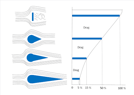
Figure 1 Form Drag (wwwaeroforum)
Interference Drag
Interference drag occurs where different airflow streams meet and disrupt each other, typically at the junction of aircraft components. When these separated airflows meet turbulence or eddy currents are created. This creates more turbulent airflow then would typically be created if only one component was separating airflow.
A classic example is the intersection of the wing and fuselage, where the airflow from the fuselage meets the airflow from the wing. These colliding streams produce turbulence and resistance beyond what each component would produce independently.
Interference drag can be minimized by using fairings (smooth, aerodynamic coverings at intersections) and by optimizing the angles at which components join, ideally avoiding perpendicular intersections. The larger the angle between the components, the less interference drag is created.

Figure 2 Interference Drag (CGS Ground School Principles Of Flight Drag)
Skin Friction Drag
Skin friction drag is caused by the friction between air molecules and the surface of the aircraft. This can include any number of imperfections, such as rivets, dents, hinges, bugs, or anything else that may lead to the surface not being smooth. Even surfaces that appear smooth have microscopic imperfections that disturb the boundary layer of air in contact with them.
The boundary layer is a thin layer of air that sticks to the aircraft surface. Within this layer, air speed increases from zero (due to adhesion) to the free-stream velocity. If the boundary layer becomes turbulent or separates from the surface, drag increases significantly.
To reduce skin friction you can:
-
Using flush rivets and smooth seams.
-
Keeping the aircraft clean and polished.
-
Minimizing protrusions from the surface.
Induced Drag
Induced drag is a direct consequence of lift production. Generally the total aerodynamic forces acting on a body is thought to have two components: lift and drag. By definition, the force acting parallel to the free stream of incoming air is considered to be drag. The force acting perpendicular to this force is considered lift. As you fly through the air, the high pressure zone under the wing attempts to move to the low pressure zone above the wing. On a wing of finite span, this pressure difference results in the high pressure air underneath moving over the outside of the wingtip and to the top of the wing. This creates a twisting motion in the air which alters the direction of the relative wind, causing the lift vector to tilt slightly aft. The aft component of this tilted lift vector is induced drag. This downwash reduces the airfoil's ability to produce lift. As a result, the aircraft be flown at a higher angle of attack to produce the same amount of lift. This moves the lift vector aft, which is induced drag.
As the angle of attack (AOA) increases, so does the pressure differential between the upper and lower surfaces of the wing. This increases lift but also strengthens the wingtip vortices, resulting in greater downwash and more induced drag. As airspeed increases, angle of attack decreases, and induced drag is reduced. As airspeed decreases, angle of attack increases, and induced drag is increased
Total Drag and Drag Curve
Total drag is the sum of parasite drag and induced drag. These two types of drag behave differently with changes in airspeed:
-
Parasite Drag increases with the square of airspeed.
-
Induced Drag decreases with the square of airspeed.
The relationship between airspeed and total drag forms a drag curve. There is a specific airspeed where total drag is at its minimum—this is known as the best glide speed or minimum drag speed, which is crucial for maximizing range or endurance in unpowered flight.

Figure 3 Drag Curve (Boldmethod)
Wingtip Vortices and Wake Turbulence
Wingtip vortices are the visible result of induced drag and form whenever lift is produced. The strength of these vortices is:
-
Directly proportional to aircraft weight.
-
Inversely proportional to wingspan and airspeed.
Strong vortices pose a danger to following aircraft, especially during takeoff and landing. An aircraft is producing the largest vorticies when it is heavy, clean, and slow. This applies especially to the landing and departure phases of flight. These rotating air masses create wake turbulence, which can cause control problems or structural damage.
Avoiding Wake Turbulence
To reduce the risk:
-
Rotate before the rotation point of a preceding aircraft.
-
Land beyond the touchdown point of heavier aircraft.
-
Stay above the flight path of aircraft ahead.
-
Allow adequate spacing (usually 3 minutes) after a heavy or large aircraft has taken off or landed.
- Side step into the wing, if possible
Ground Effect
Ground effect is a phenomenon experienced when flying close to the ground. As you fly, wingtip vorities are directed downwards, but when the earth's surface is within, typically, one wing span, the development of these vortcies is interrupted and they dissipate before fully forming. This results in a reduction of the downwash and therefore more efficient lift generation. As a result your total induced drag decreases and the required angle of attack to maintain altitude decreases. This is typically referred to as a "float" when approaching the runway. It is important to understand this phenomenon and anticipate it when landing so as to not "float" past the point at which you can make a safe landing with the remaining available distance. It is also important to anticipate this on takeoff and not takeoff before your aircraft is moving fast enough. Sometimes when taking off, the airplane will be generating sufficient lift to become airborne, but once initiating the climb and climbing further than one wings span from the ground, induced drag significantly increases and the aircraft may stall if enough lift is not being produced.
Understanding aircraft drag is fundamental to mastering flight performance. Parasite drag and induced drag are ever-present forces acting against an aircraft's motion, each influenced by speed, configuration, and flight phase.
By comprehending how these forces interact and change, pilots can make more informed decisions regarding power settings, approach speeds, and aircraft configuration to optimize performance and safety.